This is a guest post by Branden Gunn, about building the LED Grid for our collaborative design project.
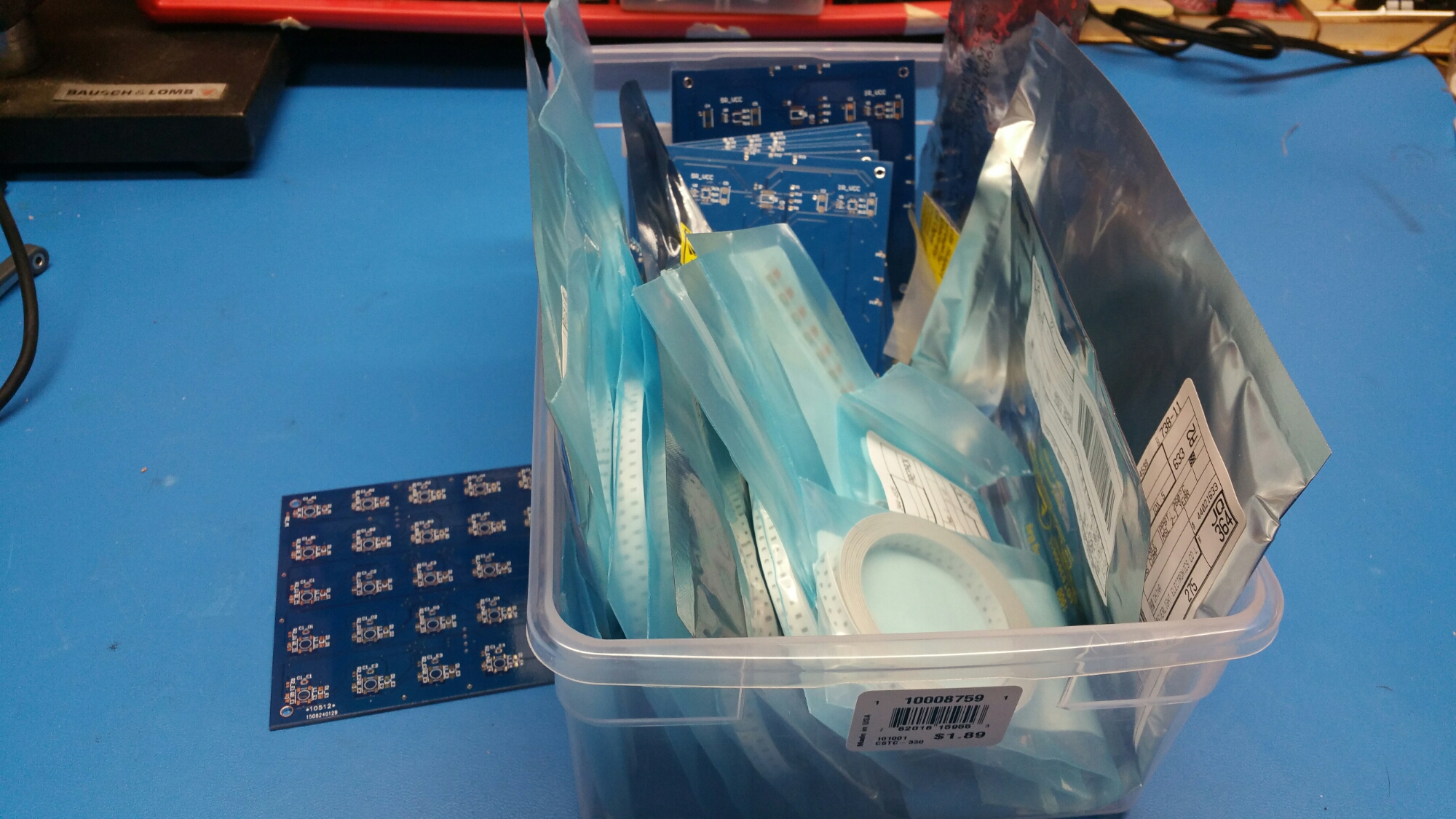
In the last post, the boards had just arrived, and the rest of the parts were on order. A few days later, everything was here! Because resistors are so cheap when you get 100 or 500, it was worth getting a few extra values to allow for testing the IR receivers.
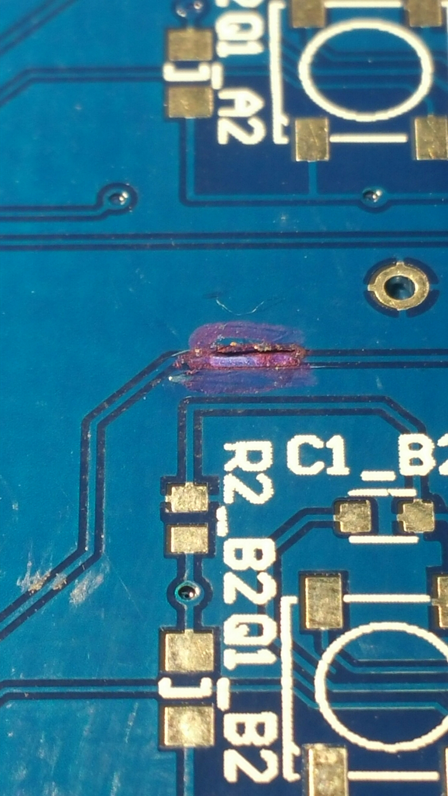
Just before assembly, I realized why DirtyPCBs are so cheap, and why they do electrical tests on all boards:
Yes, that’s blue sharpie on top of a hand repaired trace. About 30% of the boards had some kind of repair like this.
I soldered one board up and started testing. Getting the color LEDs working wasn’t a big deal, but I had problems with the IR power supply (which is also duplicated for the shift registers). It just wasn’t regulating voltage and had no output. I eventually traced it to the wrong feedback resistor setup because of a misread of the datasheet. Once that was sorted, I got started on the touch sensors.
I eventually found the right pull up resistor configuration for these, but simply could not get the shift register inputs to trigger. Because I used Schottky input registers, the sensors had to swing their output voltage through most of the power voltage range, which just wasn’t happening. With a 47K pullup, the sensors were only changing the output by about half a volt. The lowest setting the shift registers could take is 2V logic, where the difference between a low and a high is 0.8 volts.
The only solution was to alter the circuit. I decided a comparator would be the most reliable trigger, and I could put a simple pot to adjust the threshold voltage. If I need to get fancy, I can always add a feedback resistor to get a tiny bit of hysteresis. It would have been extremely difficult to bodge in 25 comparators, even on quad packages, so I decided to spin another board. I picked the LM339 for it’s low cost and simple package layout.
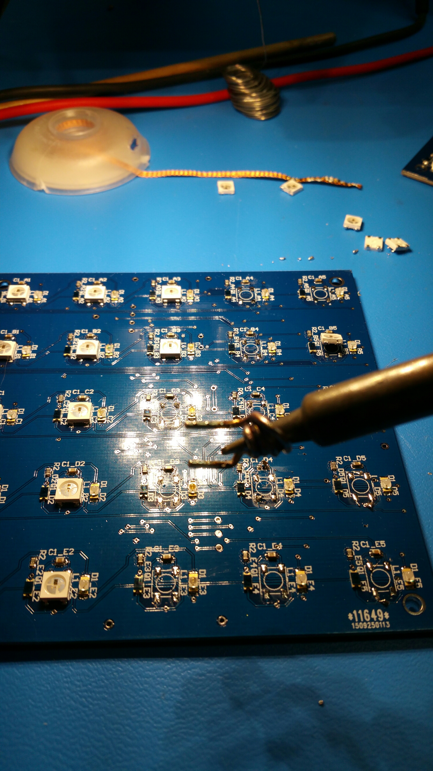
I also ordered solder paste stencils for the new revision board and ordered the LM339s. I borrowed the hotplate soldering equipment from work and put together two boards. Power on, and the bench supply trips for overcurrent… A bit of head scratching and careful looking, and I realize I managed to get all the WS2812B color LEDs on backwards. Fortunately, they all have reverse polarity protection, but getting them off was a bit of a pain. I remembered a trick I saw on Hack A Day to use some heavy solid copper wire as a crude replacement for a second iron or a tweezer iron. With this, I was able to remove the parts relatively efficiently. Most of them came off with no damage, so I tested each one and reinstalled them properly.
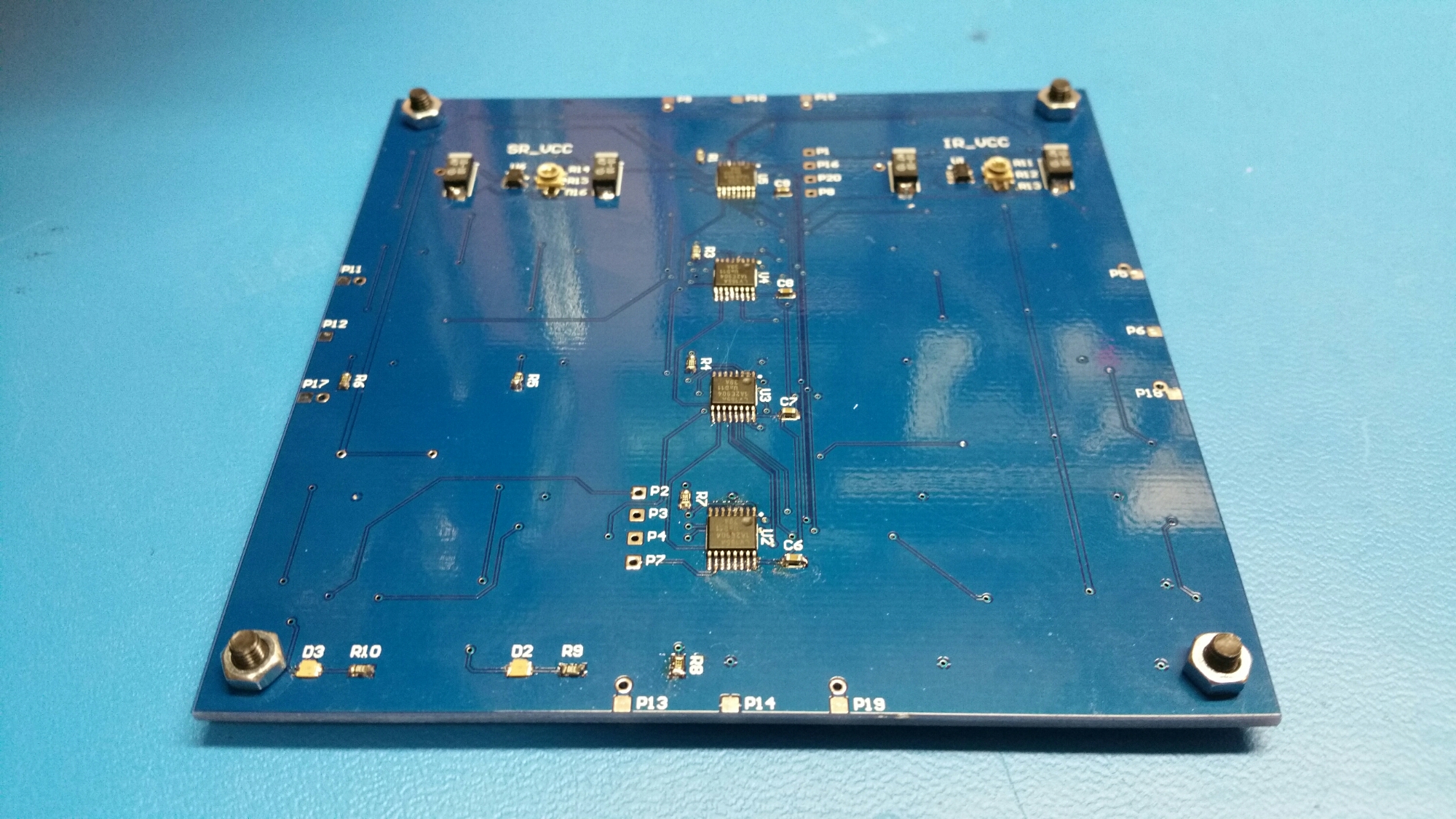
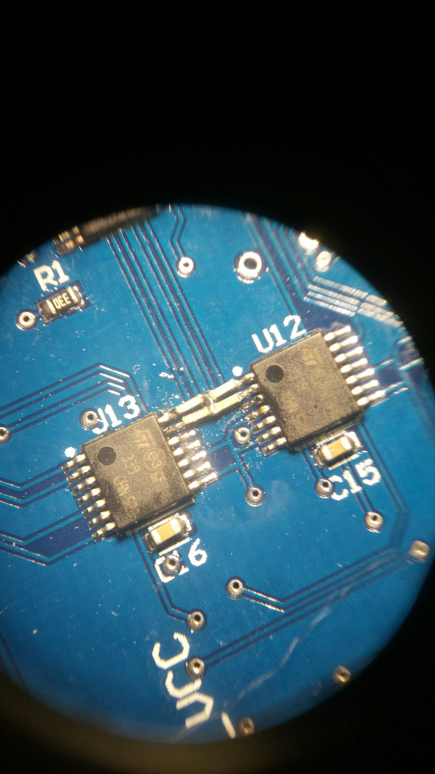
Once it was all back together again, I could finally try the new comparators. Nothing. Turns out that the lm339 outputs are open drain and don’t actually source voltage (I had been thinking of them like an op-amp). I did find a neat looking method to add 25 pull up resistors to the board without making a huge mess of it. I soldered the pull ups on edge in the space between the LM339 packages, and used two tinned strands of the finest wire I had as a trace back to the nearby power pin.
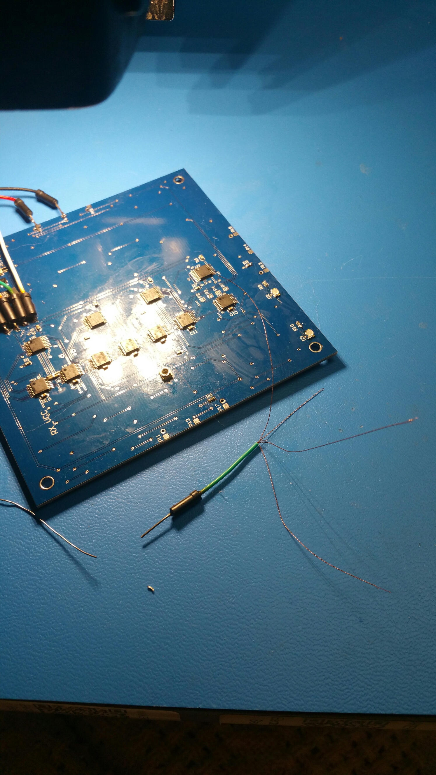
This picture shows the 7 strand wire split out into 4 two stand twisted segments, of which I need about 3mm for each set of four pull ups. The resulting work looks OK and is no taller than the TSSOP comparators, so they should be well protected.
With that working, now it’s just a matter of actual assembly into a large panel that looks good. I’ll cover that process in the next post.
