This is a guest post by Branden Gunn, about building the LED Grid for our collaborative design project
The hardware for the LED grid project consists of two major elements: The LED lights, and the IR touch system. The first idea for the board had the main LEDs spaced out in a 10mm grid. I prototyped this on some surface mount prototyping board to see if I could fit everything needed into the space available. It was a bit of a tight fit, and the nature of how I made it makes it not very pretty.
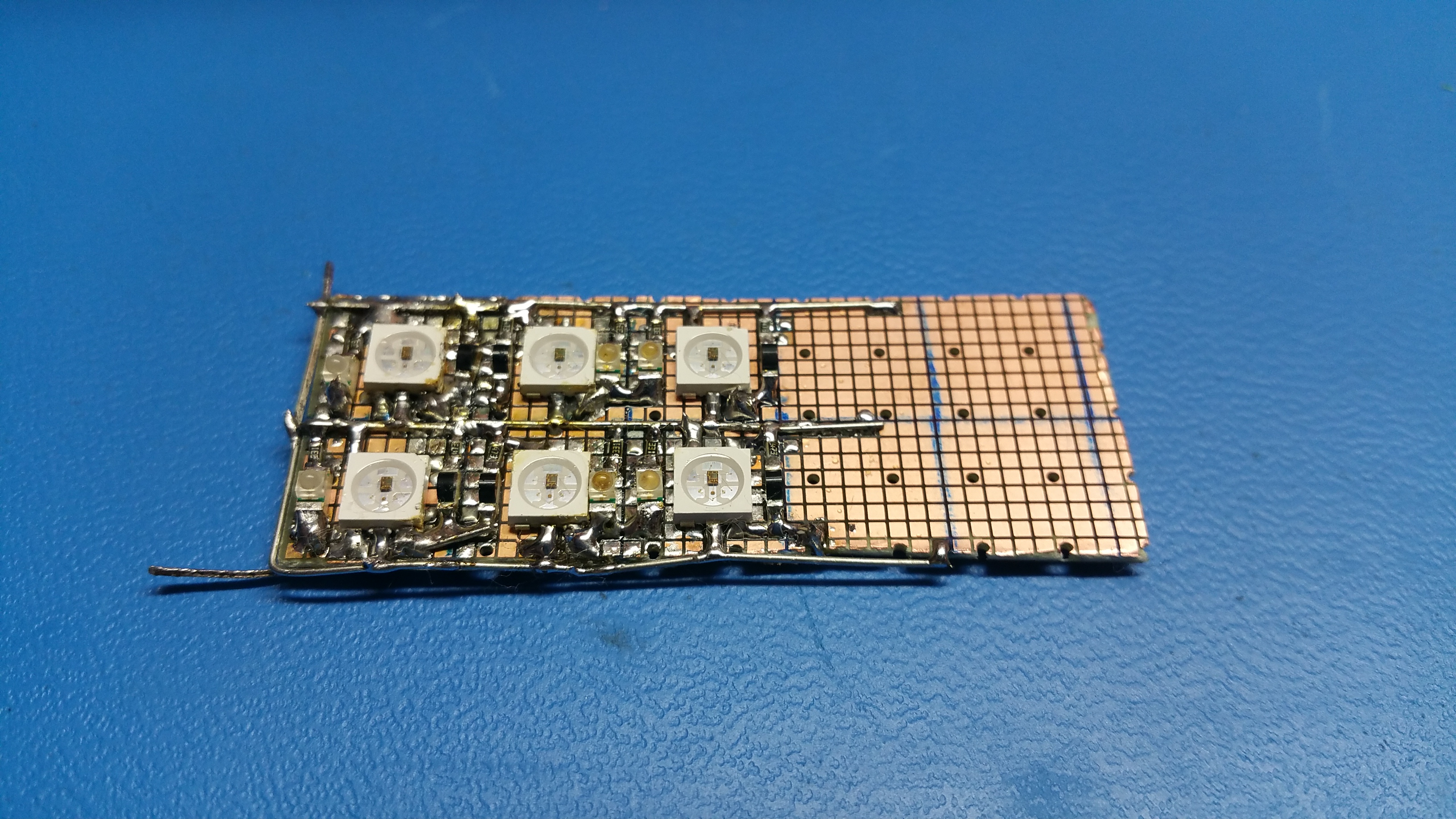
Because the LED cells were so close together, I had to alternate the IR touch transmitters and receivers in each column to keep them from interfering with each other. This was enough to prove out the concept and get initial values for the resistors for the touch system. The final design will also have adjustments for the IR LED brightness and the IR touch sensitivity, which should allow it to deal with lighting variations.
Next, the final PCB was designed. To save cost, the final project is made of 9 tiles (that are all identical) attached together into one board. We also reduced the LED count to 15 by 15 overall, meaning each tile is a 5 by 5 grid. I used Circuitmaker to draw the schematic and design the board. Circuitmaker is a free version of Altium Designer, which gave me access to some fairly powerful design tools, which certainly sped up some aspects of the design.
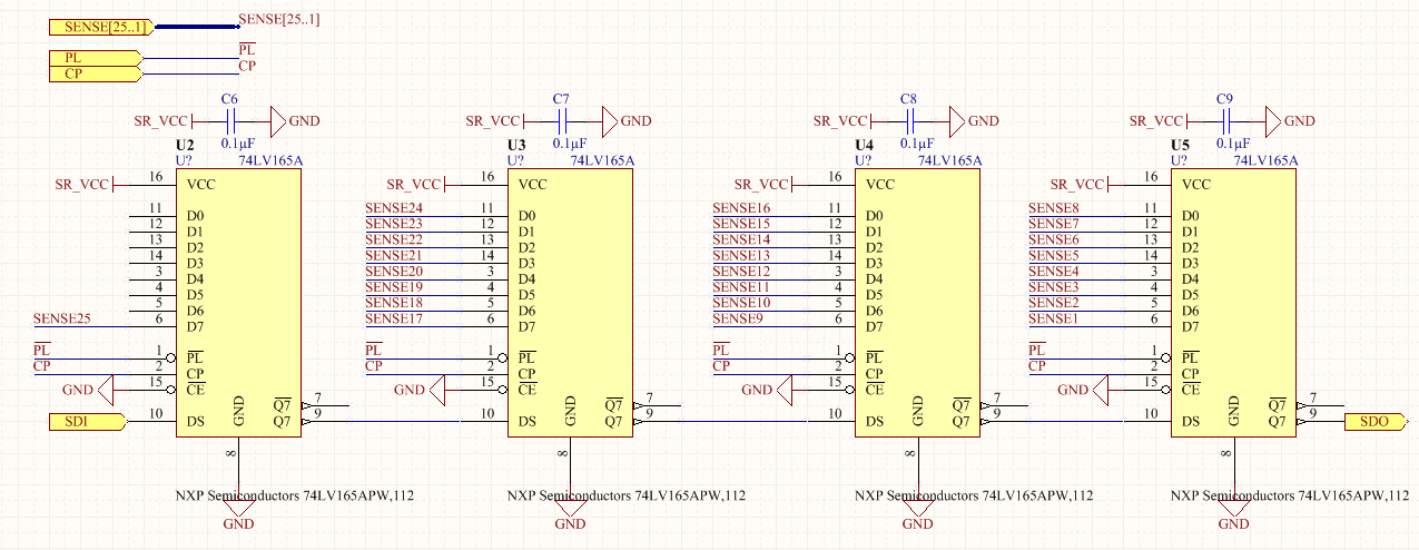
The design consists of 25 LED cells, which include the color LED and the IR touch feedback for each position on the board.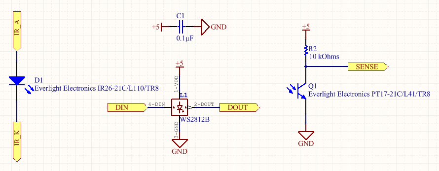 The touch feedback is passed through shift registers to make many inputs fit within a few data pins. These particular shift registers have special Schmidt Trigger inputs, which will make the touch detection more repeatable.
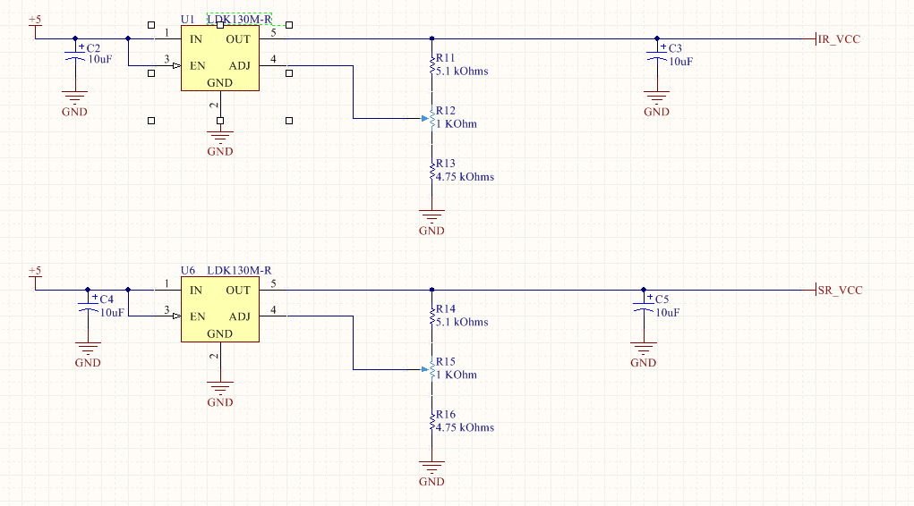
The IR LED and Shift register power supplies are adjustable, which will allow tuning of the touch sensitivity.
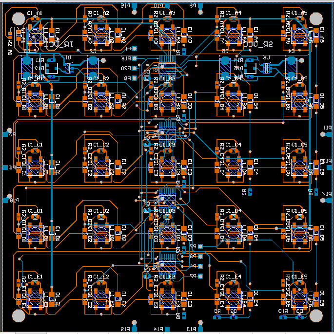
The process of laying out the board is arranging the components, and then connecting them together with wires on the PCB. Here is an early layout and the final layout, with the LED cells spaced in a 20mm grid. I ended up not alternating the IR transmitters and receivers as I had done on the prototype. I think the cells are far enough apart, and we’ll be able to fit a good wall between them to block stray IR. Red items are on the LED side of the board, and blue indicates components on the back side.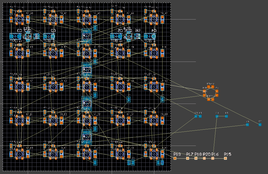
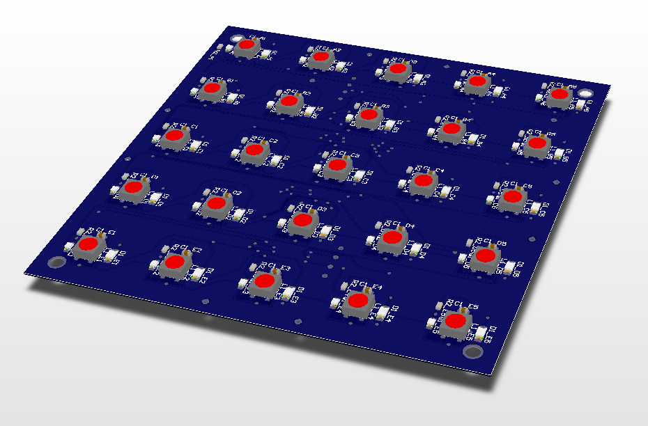
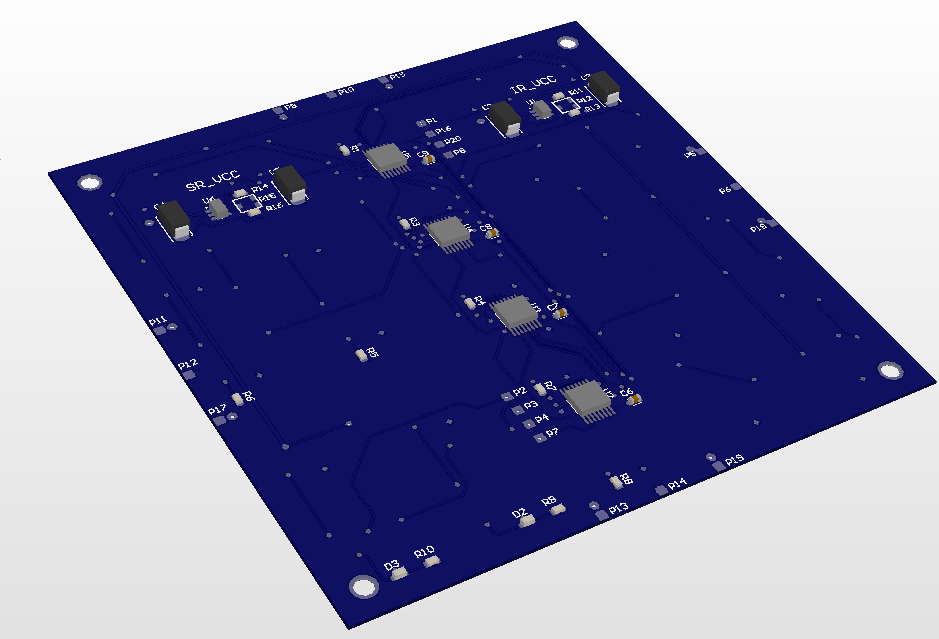
Circuitmaker also creates a 3D view of the board so you can see how it will look assembled
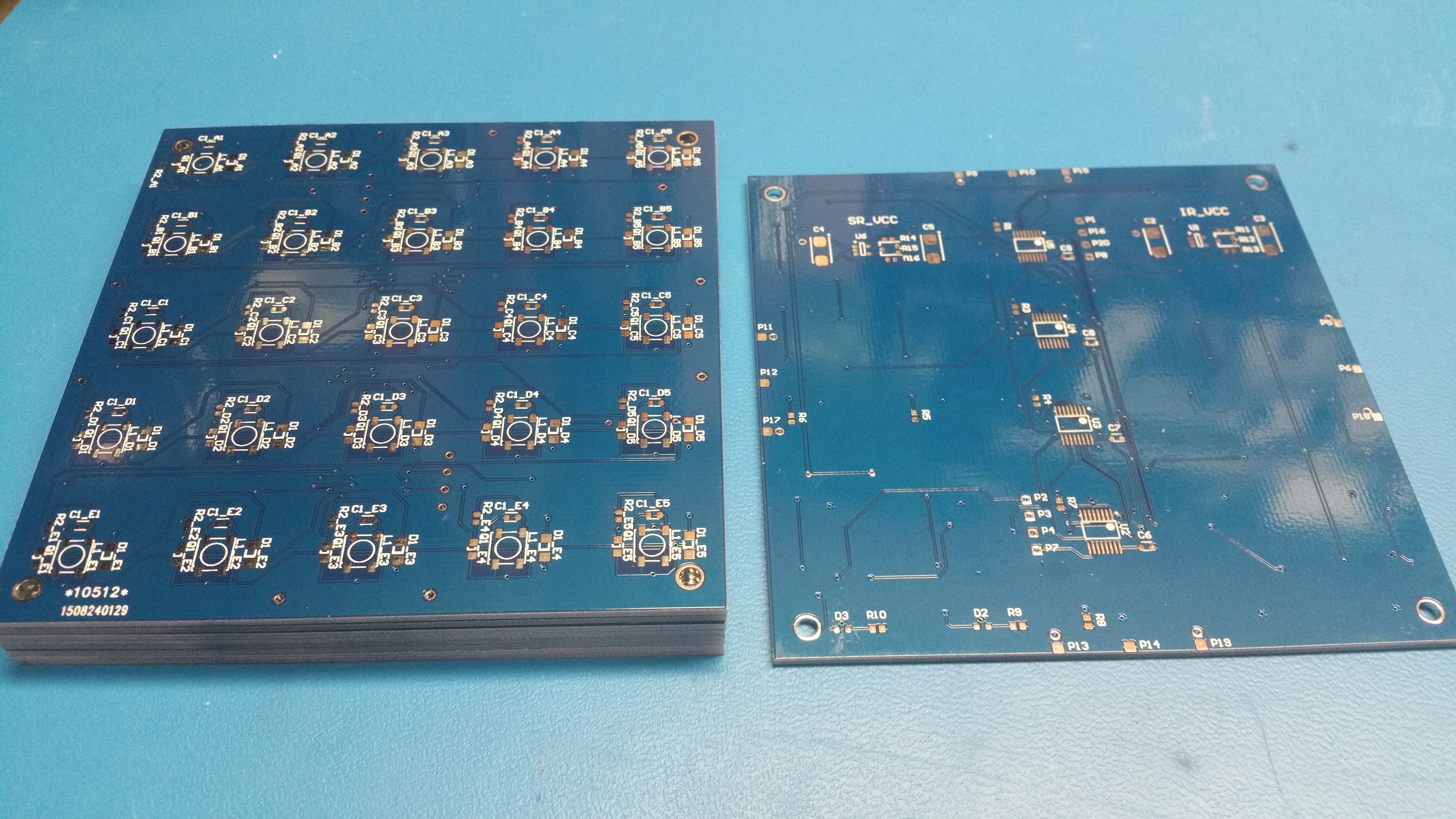
The circuit boards arrived first this week (ordered from Dirty PCBs), and the rest of the components are already in the mail.
Here’s a timelapse view of the layout and wiring of the board (the last 4 hours of work) condensed to 100 seconds.